
To study space weather, which includes
| To collect data pertaining to
|
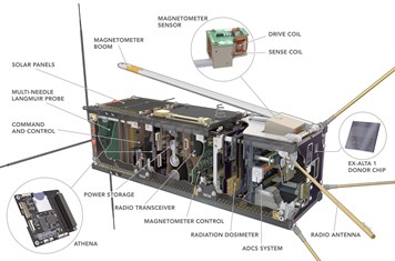
Ex-Alta 1 had four payloads:
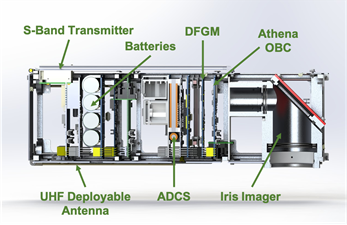
| Ex-Alta 2 has two payloads:
|
The importance of studying space weather
Space weather affects the health of satellites in orbit, radiation exposure of personnel in airplanes, power infrastructure on Earth, and life on Earth in general.
Objective: To obtain data that will further our understanding of space weather, ultimately helping us predict and prepare. | The importance of studying wildfires
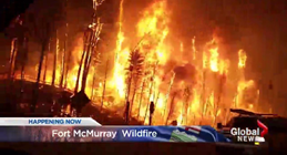
Wildfires lead to burning of millions of acres of land across the world every year. For example, about 4.7 million acres were burned in the year 2019 alone. This dramatically affects many communities across the world. Additionally, rising global temperatures are leading to an increase in the number and intensity of wildfires every year.
Objective: The data collected will help us better understand the start and spread of wildfires so we can better prevent disasters like the one Albertans saw in Fort McMurray in 2016. |
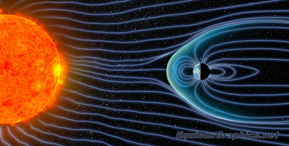
Ex-Alta 1’s scientific mission was to study space weather using a Digital Fluxgate Magnetometer with the notion of how it can severely impact Earth’s magnetic field. Relative to Earth, space weather refers to changes in the space environment dependent on solar activity.The following image by the European Space Agency provides a visual summary of how changes in solar activity can affect us. 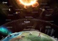
The sun’s magnetic field goes through a cycle (solar cycle) in which it flips on itself every 11 years. The activity varies from cycle to cycle, but the probability of geomagnetic storms occur near the peaks of the cycle . According to NASA, since December 2019 we are currently in cycle 25 with another solar maximum predicted to be in year 2025. The image below shows the sun during solar maximum(left, April 2014) and solar minimum(right, December 2019) during our current cycle. 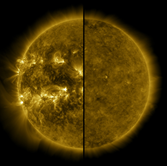
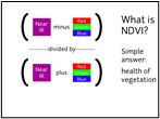
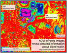
| Ex-Alta 2’s Inclusion of the in house Iris pushbroom style multispectral imager will enable us to analyze spectral bands required to calculate multiple spectral indices, for example normalized difference vegetation index (NDVI) and normalized burn ratio (NBR). These indexes play an important role in creating accurate fire severity assessments for prevention and prediction. NDVI: Normalized difference vegetation index is calculated using the visible and near infrared light that is reflected by vegetation. Usually healthy vegetation absorbs quite a lot of visible light leaving a strong NIR (Near Infrared) reflectance signature [Ceccato et al., 2002]. Following this logic, areas with a lesser density/unhealthy vegetation give a stronger visible light (red/green/blue) reflectance signature. Processing data using the formula presented below gives an output of either -1 or +1. Areas of dense vegetation will have values close to +1 while a lack or absence of vegetation will be close to zero. Ex-Alta 2 will be using bands of 620-670nm and 840-880nm to determine NDVI ratios.
NBR: Normalized Burn Ratio uses the calculated ratios of short wave Infrared (SWIR)reflectance and near infrared (NIR) reflectance to identify burned areas and quantify the burn severity.SWIR helps identify changes in water content and soil exposure [Jensen, 2000; Lillesand and Kiefer, 2000] while NIR is sensitive to the vegetation density/biomass [Ceccato et al., 2002],
With this information we can eventually calculate a normalized dynamic burn severity of the landscape by subtracting the pre-fire ratio from the post-fire ratio [Key and Benson, 1999, 2005],
|
|
 |
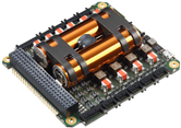
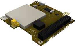
GomSpace P31uS NanoPower electrical power system (EPS) 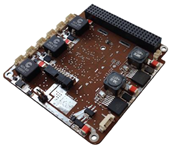
Battery:
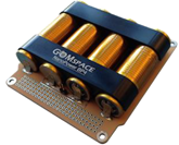
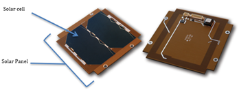
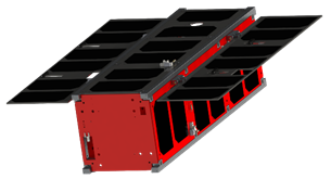
Solar Panels:
  | NanoAvionics Electrical Power System “EPS”
Battery:
Solar Panels:
 |


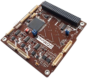
OBC for Ex-Alta 1:
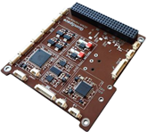
| OBCs for Ex-Alta 2: Athena:
COTS OBCs: Backup system
The 3 OBCs listed above are being considered alongside Athena as the OBC put into Ex-Alta 2.  |
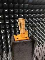
Surrey Space provided the CubeSpace Y-momentum ADCS. It controlled the orientation of the satellite using three magnetic coils and one weighted reaction wheel. It consisted of:
GPS:
| Ex-Alta 2 will use the CubeSpace 3 Axis ADCS, which consists of:
Ex-Alta 2’s GPS isn’t interfaced through the ADCS GPS: The GPS system integrated with Ex-Alta 2 will be made up of two components
|
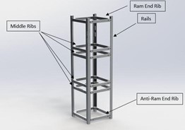
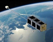
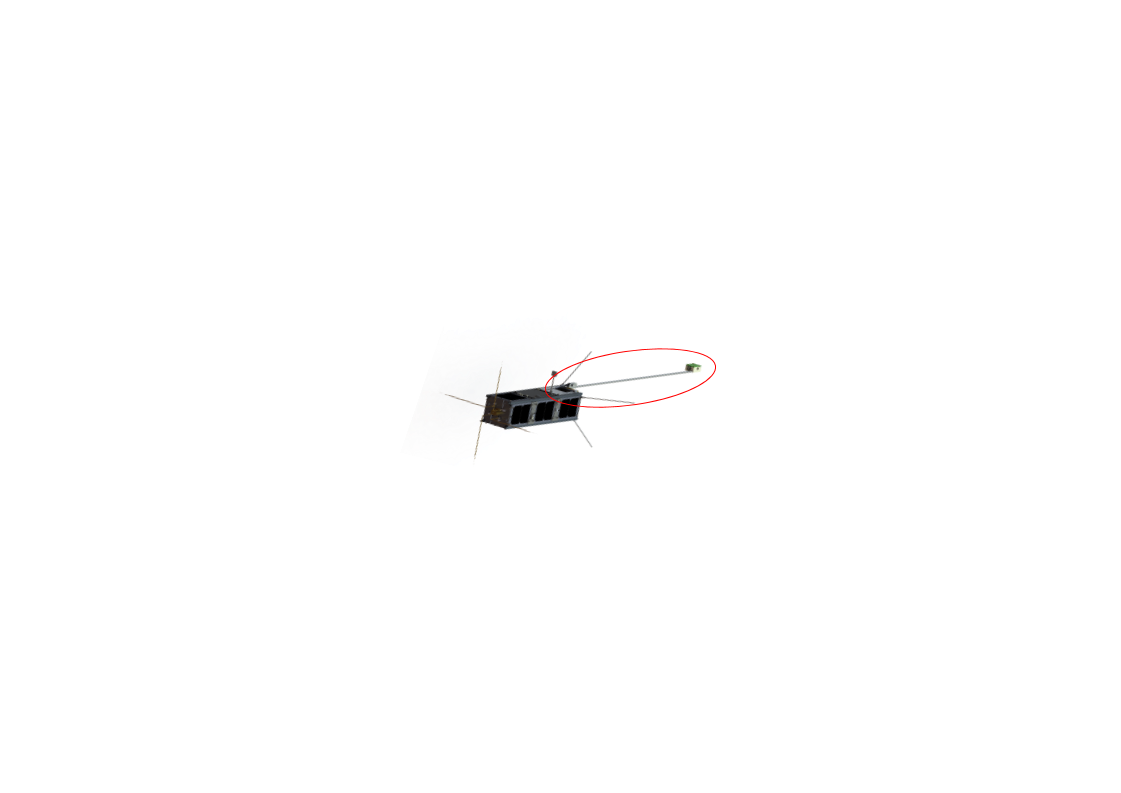
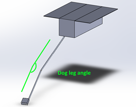
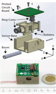
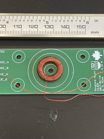
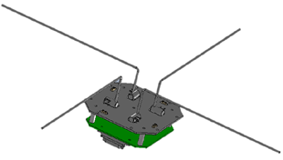
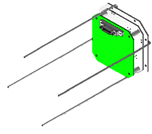
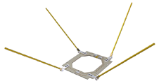
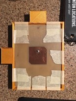
Magnetometer boom:
  |
  |
Payload: Multi Needle Langmuir Probe (MNLP) Purpose
Specifications
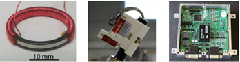
MNLP boom system:
MNLP electron emitter:
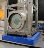
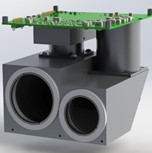
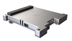
 | Payload: Iris Imager
Parameters of image data
Specifications:
| |||||||||||||||||||||||||||||||||||||||||||||||
Communication between Ex-Alta 1 and Ground Station was only via Ultra High Frequency (UHF) Band UHF Band:
  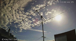 | Communication between Ex-Alta 2 and Ground Station is via Ultra High Frequency (UHF) and S-Band UHF Band:
 S-band:
|
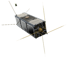
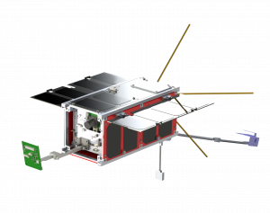
Orbited the Earth at an altitude of 415 km for up to 18 months before burning up during re-entry. Launched to the International Space Station (ISS) April 18, 2017 from Cape Canaveral Air Force Station and was deployed from ISS on May 26, 2017. Its work ended on November 14, 2018. Averaged 4 to 5 passes over Edmonton per day. | Set to orbit the Earth at a maximum altitude of 410 km for 1-2 years. Currently in the works and set to launch in March 2022. Based on Satellite Tool Kit (STK) simulations, there will be 5 passes a day (only for the case of UHF passes). |
| Total Program Cost: $500,000 | Estimated Program Cost: > $500,000 |