Hermes S-Band Antenna

Hermes S-Band Antenna is a microstrip patch antenna (MPA) in the currently developed Ex-Alta 2 cubesat. It has four main parts:

Part Definition Function
1) A radiating patch (technically the antenna)
The patch is a thin sheet of conductive material.
It radiates electromagnetic waves and acts as an antenna.
2) A ground plane
Ground plane is typically a sheet of conductive material same as that of the patch.
The ground plane sits below the radiating patch.
3) A dielectric substrate
The dielectric substrate separates the patch from the ground plane.
Provides a medium for electric fields to form.
A feed (microstrip feed)
The microstrip feed connects the antenna's radiating patch to its ground plane. The load attaches to the feed.
The feed provides power to the antenna. It transmits the information to and fro from the load to the patch.
The basic structure of the microstrip patch antenna
915MHz Patch Antenna Saturn PCB Design (https://saturnpcb.com/pa915/)

Photos

Working of Hermes S-Band Antenna

Working Pictorial Representation
  • Working principle: Ampere's Law = a current-carrying element or antenna creates a time-varying magnetic field which then creates a time-varying electric field and so forth to generate a free-space electromagnetic wave.
Source: http://fab.cba.mit.edu/classes/862.06/students/alki/EMprop2.jpg
Concept and Working principle of an antenna showing how an a) antenna (current carrying element) can create b) electromagnetic wave that carries information
  • When the antenna is attached to a load, it radiates the load's information in an energy-storing electromagnetic wave.
  • The reciprocity of the antenna dictates that an antenna can equally do the vice-versa i.e translate a free-space electromagnetic wave into guided electrical wave.
  • Thus, Hermes S-Band Antenna will be able to transmit and receive information to and fro from the Ex-Alta 2 satellite in space and ground station on Earth.
Representation of information transfer between cubesat antenna and ground station antenna
(https://directory.eoportal.org/documents/163813/5473762/CUBIT_Auto8.jpeg)
  • Microstrip patch antennas radiate due to the fringing fields created between the patch and the ground plane and resonate according to the dimensions of the radiating patch. Specifically, the length of the radiating patch determines the resonant frequency as follows:

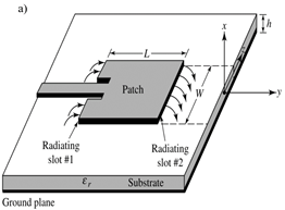
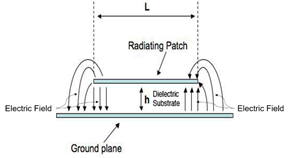
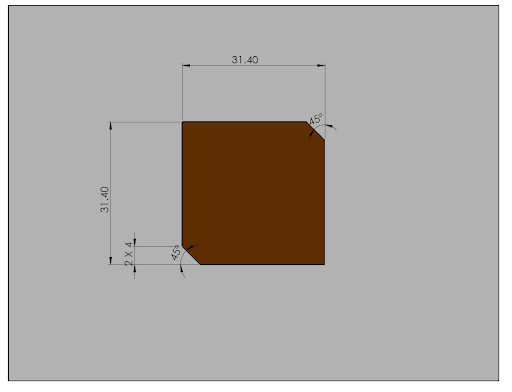
W = L = (c/2fr)* [2/(εr+1)]1/2

  • W, L = width & length of the patch
  • For circular polarization: W = L 
  • c is speed of light in vacuum
  • ɛr is dielectric constant of substrate at resonant frequency fr
  • Hermes Antenna is designed for operation in the S-Band range :
    • Bandwidth: 2.2 to 2.3 GHz
    • fr  =  2.25Ghz
Radiating patch antenna (http://fab.cba.mit.edu/classes/862.06/students/alki/patch.jpg)

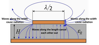
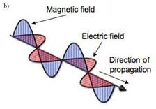
Generation of fringing-fields is as follows:

1) When current through the microstrip feed line reaches the patch antenna, then electromagnetic waves are generated.

2) The electromagnetic waves are generated in the dielectric substrate, not in the patch antenna.

3) As the thickness of the patch is extremely small, the waves that are produced within the dielectric substrate get reflected by the edge of the patch. The continuous structure of the patch along the length does not permit the emission of radiation.

4) The electric field is zero at the centre of the patch, maximum (positive) on one side, and minimum (negative) on the opposite side. These minima and maxima continuously change side like the phase of the RF signal.

5) The electric field does not stop abruptly near the patch's edges like it would in a cavity: the field extends beyond the outer periphery. These field extensions are known as fringing fields and cause the patch to radiate.

Generation of electromagnetic radiation, Source: https://www.radartutorial.eu/06.antennas/pic/patch1.print.jpg

Design Considerations for Hermes S-Band Antenna

Chose Right Hand Circular Polarization (RHCP)

Why is it needed and what do we need from it?

  • Difficult to control satellite  orientation very precisely in space
  • Want the patch antenna to not be restricted by needing to be aligned in parallel with receiving antenna 
  • Circular Polarization (either left or right hand) remove the need for antennae to be parallel

How will we achieve this?

  • Two orthogonal fields of equal magnitude but 90° out of phase must be generated. Can be done via either of:
    • Multiple Feeds
    • Perturbation on patch

Chose Rectangular

Why is it needed and what do we need from it?

  • Needs to enable RHCP
  • Want antenna to maximize gain
  • Antenna dimensions need to match resonant frequency

How will we achieve this?

  • Carefully placed notches need to be placed on the antenna to change its radiation pattern, creating RHCP
  • Rectangular patch has larger area which means higher gain and is easier to manufacture

Chose coaxial feed

Why is it needed and what do we need from it?

  • Connection must be to the back of antenna
  • Coaxial feeds usually has characteristic impedance of 50 ohms (which makes it easy to match)

How will we achieve this?

  • The placement of the feed relative to the notches to the antenna determines whether it is RHCP or LHCP (left hand circularly polarized)

Range of 2.2 to 2.3 GHz

Why is it needed and what do we need from it?

  • Must be compatible with NRCan stations that it will downlink to

How will we achieve this?

  • Exact bandwidth and resonant frequency will be chosen upon licensing

Simulation Result for Hermes S-Band Antenna

Frequency Range2.2 – 2.3 GHz
Half Power Beam Width (HPBW)>60°
PolarizationRHCP
Feed typeSMA
Impedance50 Ω
Frequency Range2.19 – 2.3 GHz
Half Power Beam Width (HPBW)90° (at resonant frequency 2.25 GHz)

Gain

2.3 dBi (at resonant frequency 2.25 GHz)

PolarizationRHCP
Impedance50 Ω
Frequency Range

2.18 – 2.28 GHz

Half Power Beam Width (HPBW)

74°

Gain

4.5 dBi (over operational bandwidth)

PolarizationRHCP
Impedance50 Ω

Mass

30.97 g

Dimensions in 2D
Dimensions in 3D

*Final simulations and fabricated antenna design parameters are subject to future changes depending on licensed frequency of operation.

By Helena Ard, Akki Sahoo, Sam Belau and Anirban Mistry

This page was last updated March 2021