
Icarus Structure Design
What is the Icarus Structure?
The Icarus structure is a specifically designed assembly meant to be used in conjunction with AlbertaSat’s 3-unit Cube Satellite, Ex-Alta 2, as it’s bus component. As the Icarus structure was designed in house, accommodations for Ex-Alta 2’s internal components’ unique requirements were able to be made and costs associated with the construction were drastically reduced.
Materials:
Aluminum 6061 T6
A commonly used aluminum alloy in the aerospace industry due to its easy extrusion and forming into complex shapes. Commonly referred to as structural aluminum, 6061 offers very good corrosion resistance in addition to high strength and is lightweight, making it very attractive to aerospace applications [https://www.gabrian.com/6061-aluminum-properties/].
It will be used to form the ribs, rails, and rods of the Icarus bus
Specs:
External Dimensions of 100mm x 100mm x 340.5mm (Conforming to the standards laid out by NanoRacks)
Mass of 0.306kg, lightweight due to use of Aluminum 6061 T6 alloy (for weight reduction)
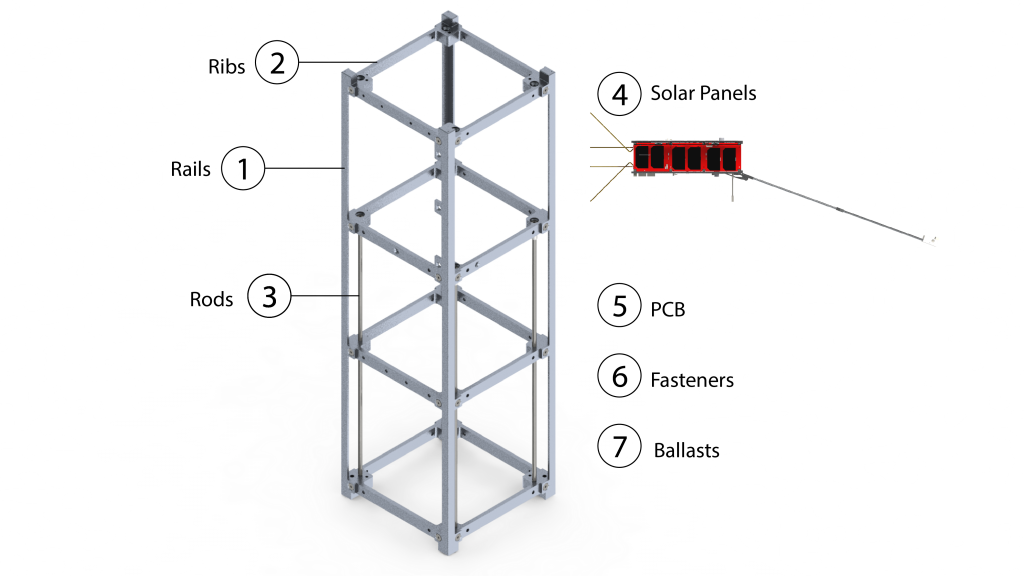
Stack Configuration:
4 rails interfacing with the NanoRacks CubeSat Deployer
4 ribs interfacing with the rods and in turn interfacing with the stack
Solar panels mounted on the body & Nadir board
Printed Circuit Boards (PCBs) mounted on 4 rods
Stack built up from Anti-Ram Rib
7mm (anti-ram) threaded ends on rods to allow for interface with standoffs and anti-ram rib (respectively)
Washers and Spacers separate PCBs on the rod
- Along the z-axis
- Rails adjoin top and bottom corners of the payload (ie. Top right corner of top face is adjoined with bottom right corner of bottom face)
- Minimum width of 6mm on x & y faces
- Fillet Radius of 0.5mm +/- 0.1mm
- Completely bare with minimum cross section of 6mm x 6mm
- Length of 340.50mm (+/-0.1mm)
- Ribs are continuous (no gaps, holes, fasteners, etc.) other than on tabs that extend outward in order to interface with the ribs and other components (ie. The iris)
- Four ribs will support and connect the rails of the bus structure together
- The separation between each rib will be close to 100mm but may vary depending on design requirements
- The four ribs essentially divide the cubsate into 3 units
- Four rods will run aligned with the four rails spanning the length of 2 units of the CubeSAT
- These rods are used to affix and mount the PCBs
- Each rod is threaded at each end to interface with the standoff and anti-ram rib
- Deployable
- Solar panels are 2mm thick and 60cm2 in surface area
- Made up of 2 solar arrays consisting of 3 solar cells each
- Weight of 50g
- Iris will form the main hardware of the CubSat and PCBs will be used to support Iris by providing communication, updating position, etc.
- Will be mounted by the rods in the 2 units closer to the anti-ram face
- Washers and space will be inserted on the rods between each PCB
- Used in tandem with HeliCoils & Loctite
- HeliCoils are more resistant to wear than material used for ribs & rails
- HeliCoils selected based on criterion to avoid cold welding
- Solid state fusion of similar metals
- The ballasts consist of a machined metal shell with a high-density core.
- A soft space-grade silicone material is used to separate ram ballast from Arke UHF phasing board to prevent vibrational damage
- Gap between anti-ram ballast and anti-ram end-plate functions for the same purpose
- Fasteners are standard m2.5 thread
- Ballasts are attached to the ram and anti-ram ribs
By Tyler Iglesias, Adam Cruse, Dylan Fu and Elan Andison
Edited by Ashik Hredoy
This page was last updated November 2022