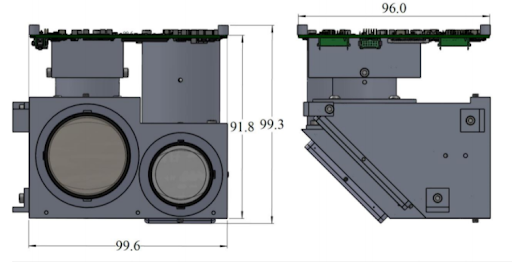
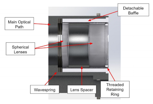
Iris is integrated into Icarus, the cubesat structure, so that both apertures are on the outside face of the cubesat and fit into one unit. The structure is made of Aluminum 6061 T6 and ensures that the optical elements remain in place and are properly attached to Icarus in two places.
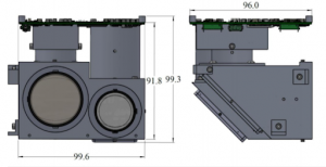
- Physical Dimensions of Iris (units in mm)
The structure houses both the VNIR and SWIR paths, and includes a 45 degree folding mirror for each. The optical pathways and main pathway are rigidly connected to the main housing.
The fasteners used in the optical paths are secured with blind threaded holes and helicoils inserts are embedded into them to avoid the use of nuts and strengthen the threads.
There are special machined holes in the main optical pathway that serve multiple purposes. Some are injection holes for epoxy that is used to pot the lenses and spacers. Others are threaded for screws to hold the baffles in place, and others are to mount the folding mirror along with compression springs.
The lenses are mounted using a detachable baffle that sits inside the primary optical path. The lenses are layered in between a wave spring and a threaded retaining ring that interacts with the baffle. This allows the lens position to be slightly adjusted, and are able to move a maximum of about +/- 0.5mm from the original position.
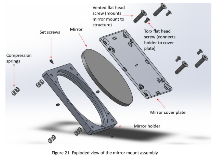
The mirrors will be mounted using a simple design. The mirrors are made of fused silica, are circular, and have a thickness of 3mm. The set screws are placed along the middle of each mirror edge so the tips are fully in contact to minimize the distortion possibilities. The mirror itself sits in the mirror holder and rests against a frame at the front and has a backing plate lined with 6 pieces of Viton cord stock for support against vibrations it will experience during launch. Minor adjustments to the mirror position can be made using the 4 threaded fasteners placed inside the compression springs.
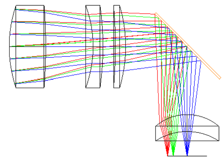
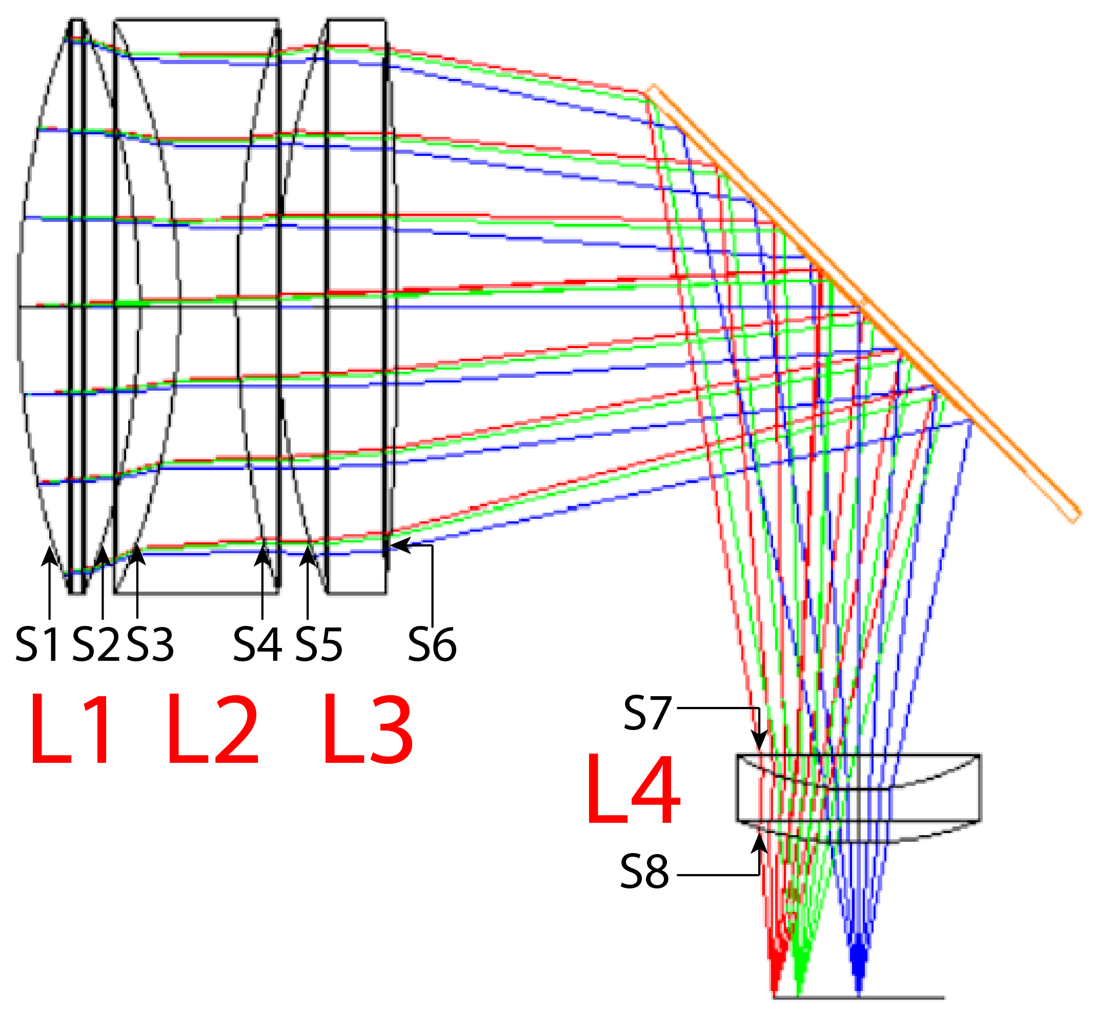
Final lens system composed of 3 commercial lens elements along with a 45° folding mirror.
| Average Resolution (400 km altitude): | 192 m |
| Average Resolution (300 km altitude): | 144 m |
| Average Modulation Transfer Function (MTF): | 0.12 |
| Effective Focal Length (EFL): | 85 mm |
| Clear Aperture: | 30 mm |
Filter Specifications
| Sensed Bands of Light: | Blue, Red, NIR (Near Infrared) |
| Overall Wavelength(s): | Blue (465-515 nm), Red (650-680 nm), NIR (845-885 nm) |
| Transmission: | 95% |
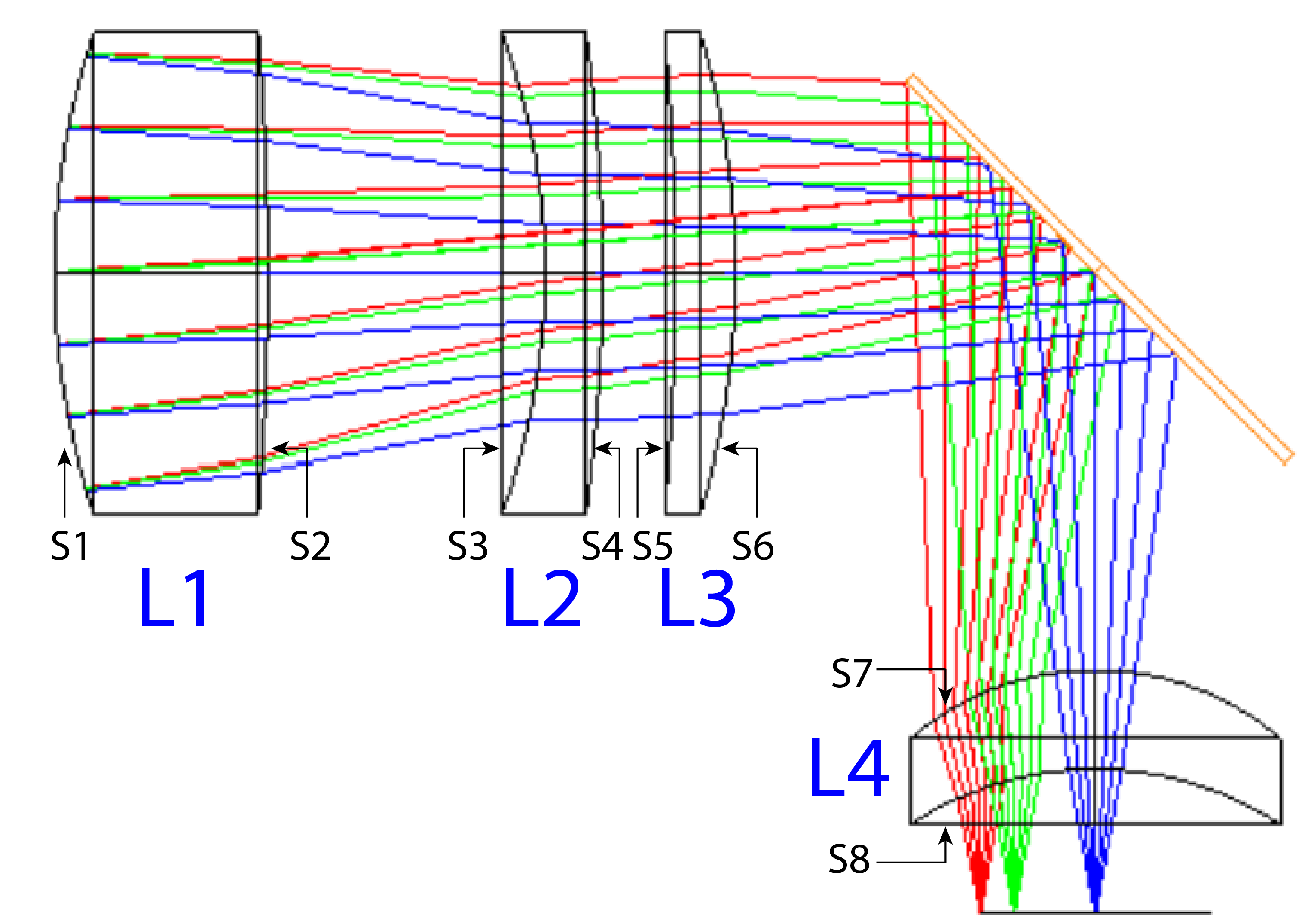 |
Mechanical Semi-Diameter (L1, L2, L3) | 16.7 mm |
Mechanical Semi-Diameter (L4) | 12.85 mm |
Clear Semi-Diameter of System (Aperture) | 15 mm |
R1 | 51.944 mm |
R2 | -205.195 mm |
R3 | -47.468 mm |
R4 | -116.564 mm |
R5 | -181.581 mm |
R6 | -57.599 mm |
R7 | -19.730 mm |
R8 | -23.439 mm |
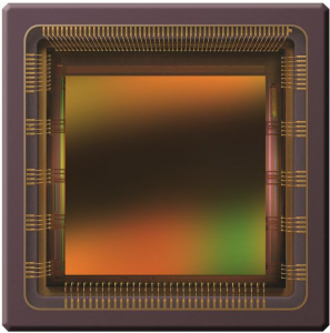
| Model: | CMV4000 (by AMS) |
| Pixel Pitch: | 5.5 μm |
The final lens system composed of 3 commercial lens elements along with a 45° folding mirror.
| Average Resolution (400 km altitude): | 358 m |
| Average Resolution (300 km altitude): | 269 m |
| Average Modulation Transfer Function (MTF): | 0.20 |
| Effective Focal Length (EFL): | 112 mm |
| Clear Aperture: | 40 mm |
Filter Specifications
| Sensed Bands of Light: | 2 – 2.2 μm |
| Overall Wavelength(s): | SWIR (Short-Wave Infrared) ~2100 nm |
| Transmission: | ≥60% |
 |
Mechanical Semi-Diameter (L1, L2, L3) | 21.5 mm |
Mechanical Semi-Diameter (L4) | 9.2 mm |
Clear Semi-Diameter of System (Aperture) | 20 mm |
R1 | 60.761 mm |
R2 | -56.966 mm |
R3 | -49.896 mm |
R4 | 74.953 mm |
R5 | 62.719 mm |
R6 | -259.960 mm |
R7 | 17.426 mm |
R8 | 24.455 mm |
| Model: | G11477-512WB (by Hamamatsu) |
| Pixel Pitch: | 25×250 µm |